Solar charger and inverter interface
SAGI Universe
August 2020
1.Introduction
In the companion background document on the Solar Charger and Interface (SCI), we mentioned that we have developed an interface that allows to remotely check the status of the unit. The interface consists of two separate units, a transmitter (TX) connected to the SCI and a receiver(RX) that can be used remotely to monitor the SCI status.
This interface collects the analogue information from the SCI, for example the solar panel voltage, the battery voltage and the 220V AC status, and transmit them to a remote terminal using a 2.4 GHz link based on a cheap interface adapter, based on the nRF24L01 chip produced by Nordic Semiconductor (ref.1). There are two types of this interface (see following pictures), one for shorter range communication and one for longer range, including also a low noise amplified and a power amplifier and a dedicated antenna. These can be purchased on many sites at a few Euros.
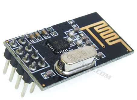
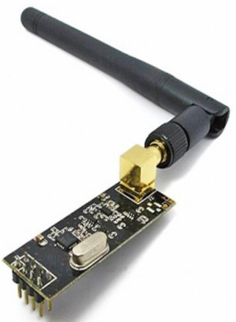
Figure 1 -Two variants of NRF24L01 interfaces (for short or longer range)
This interface is clearly useable for any other application where you need to remotely monitor analogue and digital parameters. Also, the firmware can be modified to allow, for example, two-way communication (for example to send remotely a command).
2.Interface System targets
The main objectives for the is to collect a few analogue parameters and transmit the values remotely
● Up to 4 analogue interfaces (input range from 0 to 5 V)
● Up to 2 digital interfaces (1 = 5 V, 0 = 0 V)
● Transmitter power supply obtained from the SCI (5V)
● Receiver power supply either form a battery or from the USB interface.
● Receiver unit showing parameter values on a LCD display.
● RX unit can optionally be connected to a USB port of a computer allowing for processing of the measurements on the computer.
For the design, we have used the following open-source or free tools:
● MikroC compiler (ref.2) for Microchip MCUs. This has a design limit that is not a problem for the project described in this post. However, if you want more optimized executables and no limitations, a paid version is available that costs between 200 and 250 Euro.
● KiCad (ref.3) for schematic and PCB design.
● Octave (ref.4) for various math calculations and also for serial data plotting.
All of them run on MAC Pro except the MikroC compiler. For this, a VirtualBox with Windows7 can be used.
3.Design
The NRF24L01 interface communicates with the processing unit using a Synchronous Serial Port (SSP). Therefore, the first choice was to select a PIC with this interface. The choice rapidly fell on the 16F690 chip (ref.5), as it included this interface and it is the same type of PIC used in the SCI.
The second choice was concerning the libraries for the NRF24L01. Most of the them are available for Arduino but there are some also available for PIC devices. However, considering that for this interface only the basic functions of the NRF24L01 are necessary (i.e. only simplex communication without acknowledge), we decide to write our own code to deal with this interface.
The block diagram of the TX and of the RX are shown in figure 2 and 3, respectively.
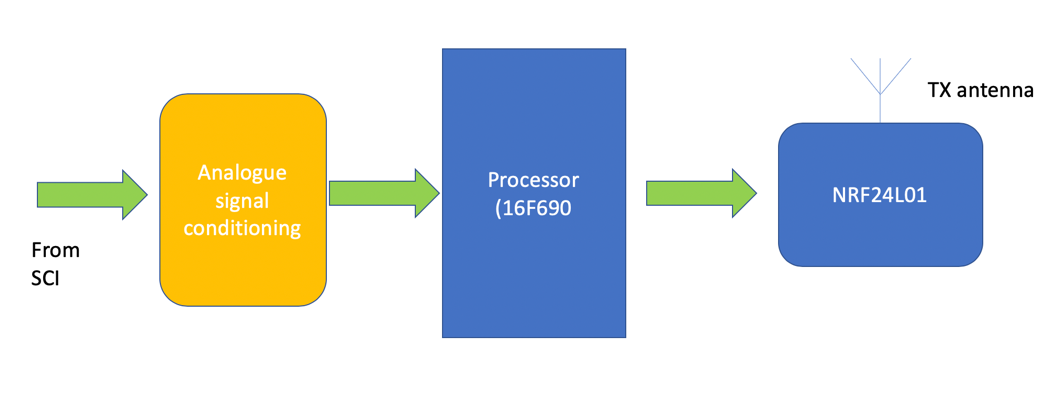
Figure 2 -TX block diagram
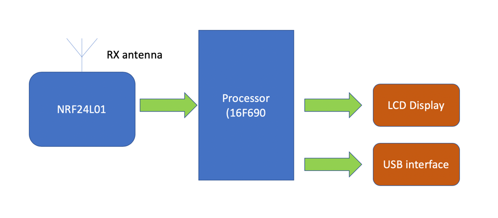
Figure 3 - 1 RX block diagram
3.6 MCU firmware
The block diagram of the TX and RX firmwares are shown in figure 4 and 5, respectively:
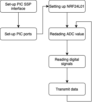
Figure 4 – TX Firmware flowchart
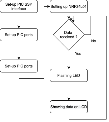
Figure 5 – RX Firmware flowchart
The firmware for both the TX unit and the RX unit startsby setting the global variables, the PIC 16F690 SSP interface and the NRF24L01 (in TX mode, for the TX unit, and in RX mode for the RX unit). Then in the TX unit, the firmware enters into an infinite loop whereby data are continuously read from the Solar Charger and Inverter and transmitted . Up to 4 analog inputs and 2 digital inputs can be interfaces: the baseline firmware default is 2 analogue and 2 digital, however can be easily modified by calling the ADC routine for two more analogue ports. Also, connection are included (see schematics later) for the RS232 PIC port that can be easily adapted to a USB port with a very cheap interface easily purchasable on many commercial sites. Once the values are read, they are transmitted by the NRF24L01.
4.Final Circuit
The final circuit schematic of the interface TX and RX units are shown in figure 6 and 7, using the circuit diagram capability of KiCad.
In both the circuits there is a 3.3V regulator to supply the NRF24L01 MCU that is based on 3.3V logics. In the TX unit this regulated voltage can also supply the PIC device (in this case the monitored voltages can be from 0 to 3.3 V). Otherwise, and additional 5 V regulator can be used as the NRF24L01 ports can in any case interface with 5 V logics.
The input ports are protected by Zener diodes (either 3.3V or 5 V, see above), series resistors and capacitors to reduce sensitivity to noise.
An ICSP connection is foreseen for re-programming the PIC.
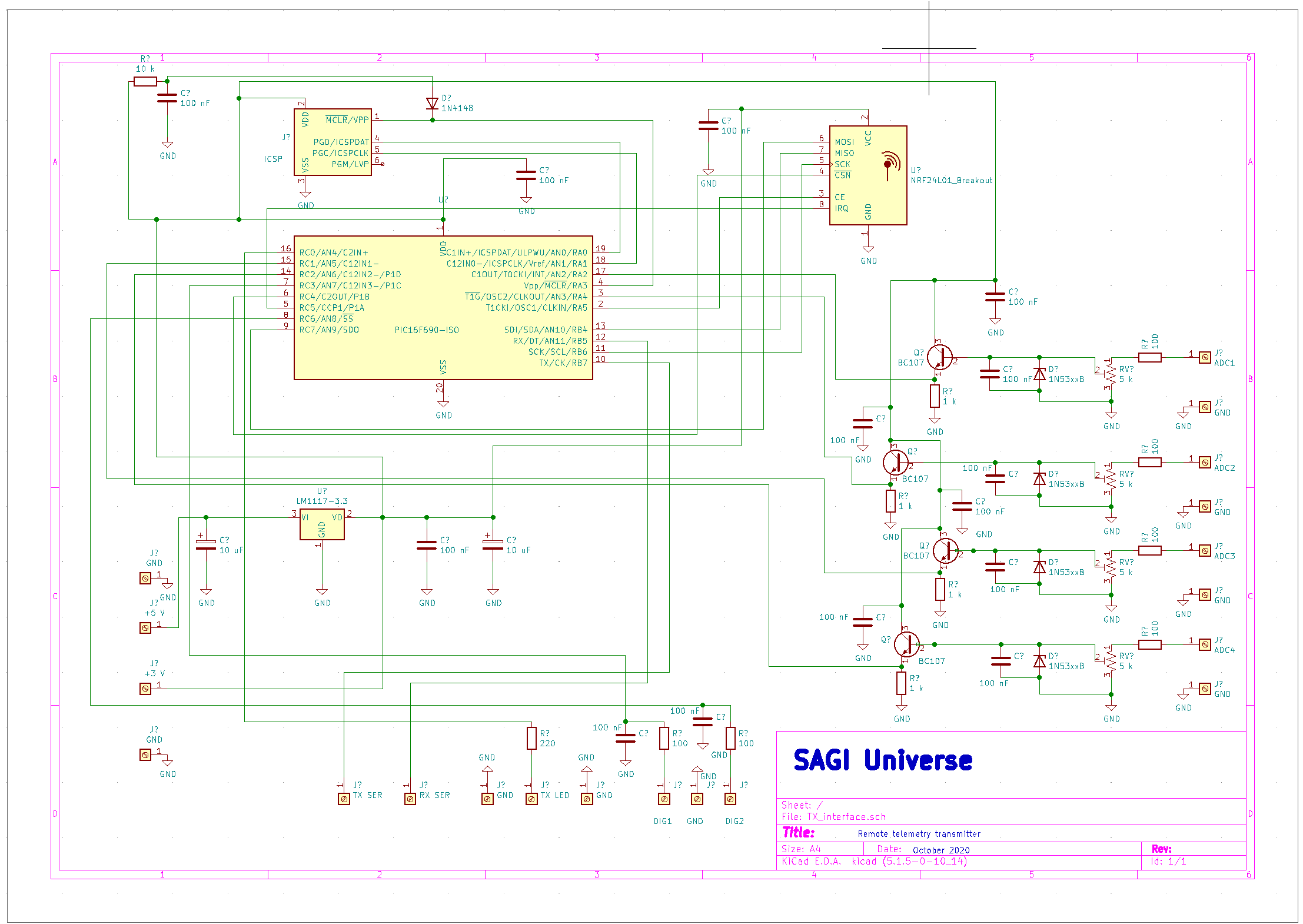
Figure 7 – TX Interface Schematic
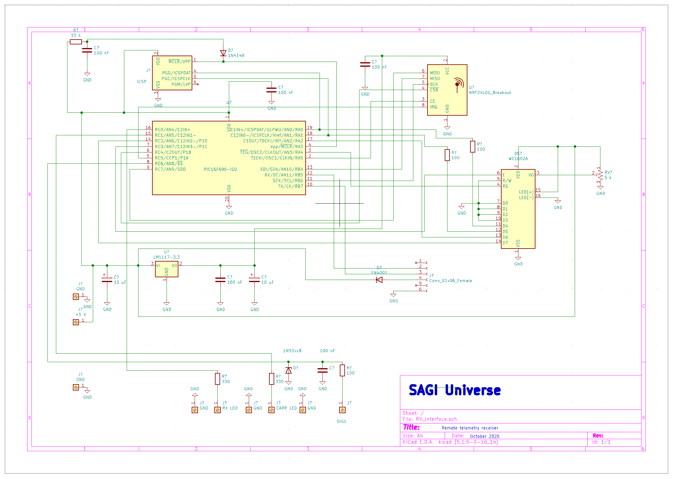
Figure 7 – RX Interface Schematic
In the RX unit, and additional connector is foreseen for connection to a RS232-USB interface (see an example in the next picture, cost is around 1-2 euros) and the unit can be powered from the USB connection instead that with a battery.
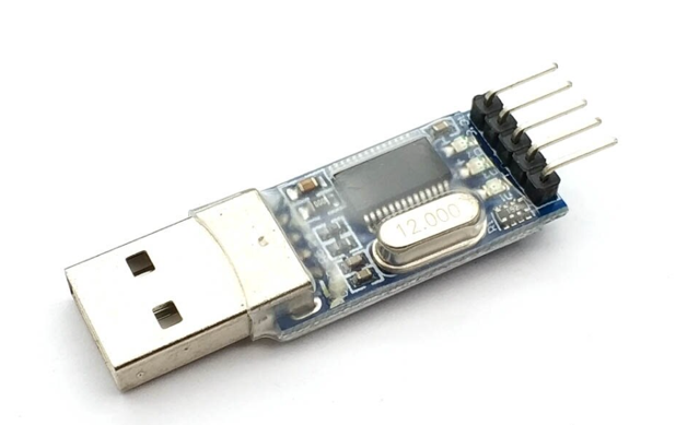
Figure 8 – RS232 - USB interface
5.Implementation and testing
Several testing units have been tried and an example of a final implementation (RX unit) is shown in figure 9. In figure 10 the TX unit is shown in operation, connected to a SCI prototype.
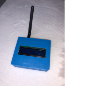
Figure 9 – RX unit prototype
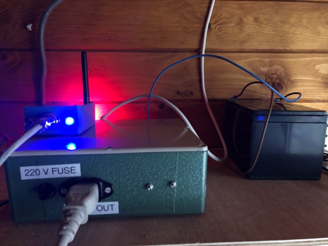
Figure 10– TX unit prototype in operation
The link between the TX unit and RX unit has been tested both indoor and outdoor, with both versions of NRF24L01 (with or without dedicated antenna). Over a distance of 15-20 m a very reliable and stable connection has been achieved with the version with antenna. However, for shorter distances we recommend to use the version without the antenna as the TX unit transmit power can otherwise saturate and block the RX unit.
Select the NRF24L01 model depending on the distance to the remote you want to reach and based on experiments especially if you want to use the TX-RX indoor. Also, select the operation frequency experimentally to avoid interferences. The frequency is settable by the firmware with a choice of 125 channels.
6.Disclaimer
The TX-RX link is not guaranteed by this interface as it is subjected to interferences and attenuation. Therefore it shall not be used for critical applications.
You can use the content of this document at your own risk. SAGI Universe cannot accept any responsibility for any injuries or damages from the use of the content of this background document.
The information contained is for educational and informational purposes only, and is made available for the reader's own use.
7.References
1. https://www.nordicsemi.com/Products/Low-power-short-range-wireless/nRF24-series
- https://www.mikroe.com/mikroc-pic
- https://kicad-pcb.org
- https://www.gnu.org/software/octave/
- https://www.microchip.com/wwwproducts/en/PIC16F690
Back